Flashing in General
The only supported method of flashing in DeityGuard is via the FTDI
UM232H
(datasheet),
a breadboard-friendly breakout board for the FTDI FT232H “bridge
chip”
(datasheet). (Note
that it is completely unnecessary to read “datasheets” as long as you
follow the instructions on this page precisely; they are only linked
here if you want to better understand how everything works).
The UM232H is plugged into a breadboard, and wires are added to
configure it and connect it to either:
- a test clip for in-circuit flashing of the
t400BIOSchip, or: - a land area for a
DIP-8chip for flashing of thed16BIOSchip.
Flashing t400 (Lenovo T400)
t400 laptops tend to
have a SOIC-16 BIOS chip, so that’s what I’ve diagrammed here. If
your t400 has the 8-pin BIOS chip, let me know via the support
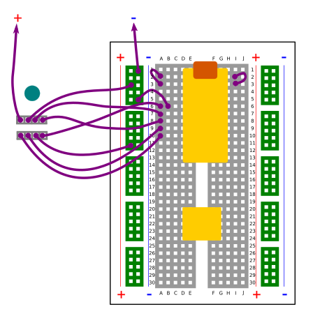
channels and I’ll create the diagram for it.Here is the schematic (or rather, “breadboardatic”):
In the schematic, the arrowed wires should lead to a 3.3V power
supply (not shown). The teal dot below the clip diagram indicates the
side of the clip that should be towards the LCD panel. Once you have
assembled it, the most convenient way to connect it is to place the
breadboard on the left side of the BIOS chip with the USB port
pointing in the other direction from the LCD panel.
Once you have assembled the breadboard, proceed to:
- unpower the
t400by disconnecting power and battery from thet400 - connect the
Pomonatest clip to thet400’sBIOSchip - turn on the external power supply
- if it has a current indicator, it should read about
180mA
- if it has a current indicator, it should read about
- connect the
UM232Hto the host computer throughUSB
Now you are ready to flash from the host system.
Flashing d16 (ASUS KGPE-D16)
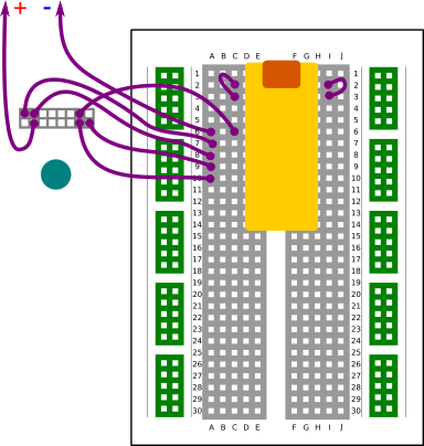
Here is the schematic (or rather, “breadboardatic”):
When wiring up the breadboard, bear in mind that some breadboards have the power and ground rails configured differently from the way shown in the diagram. It is recommended to change the wiring to match the breadboard’s indicators. If your breadboard does not have power and ground rails, you can dedicate some unused rows for this purpose.
The default BIOS chip in the d16 has a capacity of only
2MiB. After unpowering the d16, remove the default BIOS chip
carefully (in order to not damage the socket) and solder a 4MiB
SOIC chip onto a SOIC-to-DIP adapter.
Using gold-plated machine pins has the advantage that the assembly can
be inserted and removed from the socket with great ease compared to a
normal DIP chip, and the gold plating ensures good electrical
contact despite the smaller contact area.
Once you have assembled the breadboard, proceed to plug the BIOS
chip into the landing area on the breadboard and you are ready to
flash from the host system.
Flashing bpi (Banana Pi)
Not necessary! Firstly, the Banana Pi has no BIOS chip; the
SoC’s boot ROM has enough smarts to load the bootloader from the
SD card. Secondly, it is not recommended to boot from the SD card
at all since it is not possible to protect against malicious SD card
firmware. Always boot the Banana Pi through USB FEL mode.
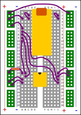
Flashing rok (Asus C201 Chromebook)
Allegedly, one must disconnect the battery before flashing this board. To do so, you must unscrew all the screws that hold the heat spreader down onto the motherboard, as the battery connector is under the heat spreader.
Getting the clip connected properly is challenging due to small
passive components soldered near the BIOS chip, but getting a good
contact can be done reliably with practice.
In the schematic, the arrowed wires should lead to a 3.3V power
supply (not shown). The teal dot above the clip diagram indicates the
side of the clip that should be towards the LCD panel.